Bolt Sets
In the Project Environment dialog, under [library or project] > Components > Bolt Sets, the project administrator can specify which types of bolt sets are available for flanged connections. A bolt set is a dimension table that defines a range of bolt sizes using the following properties: the nominal size of the connection, bolt length, bolt diameter, and the number of joint materials—bolts, nuts, and washers—to include in an instance of the bolt set.
In the piping specification, the project administrator designates which connected faces will use which bolt set, based on the nominal size of the connection. The piping specification makes the bolt set information available in the Plant Modeller session and generated reports.
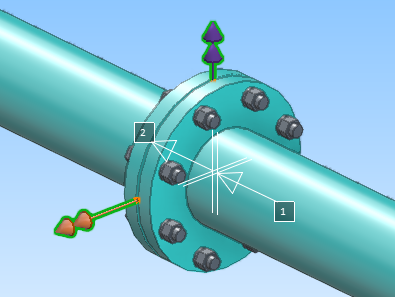
In the 3D model, an individual bolt set is visualized when the user views the connections of its host object (a flange or standard component). To visualize a bolt set in 3D, the Bolt information configuration must link the bolt set to the given connection face and its pressure rating, and the catalog parts for the bolts, nuts, and washers must have the correct Joint material attribute values.
Defining bolt sets
You can define a bolt set for a range of nominal sizes that flanged connections may use.
Prerequisites
-
Catalog Parts for the bolt, the nut, and the washer. You need their Object IDs for the bolt set definition.
Do the following:
-
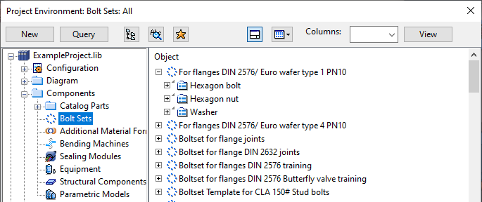
In the Project Environment dialog, browse to [project or library] > Components > Bolt Sets.
-
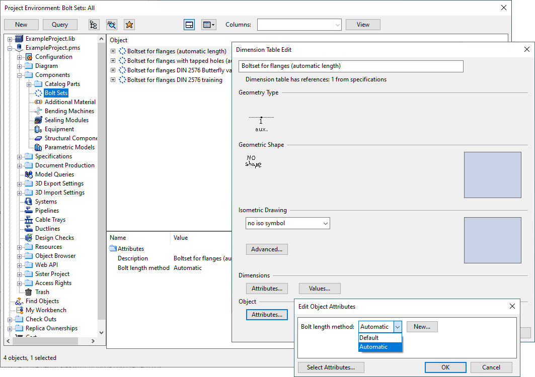
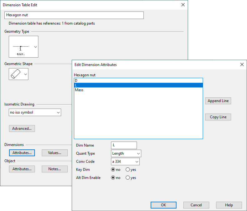
Select New > Bolt Set. The Dimension Table Edit dialog opens.
-
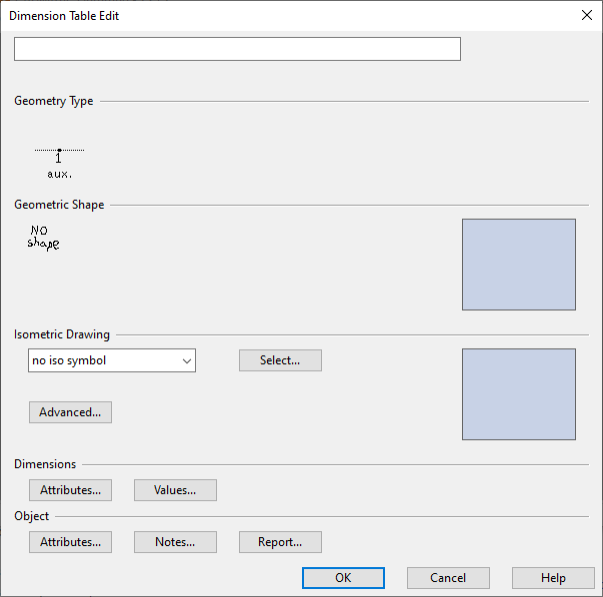
Enter a descriptive name for the bolt set.
-
You can skip the following settings:
-
Geometry Type – This is automatically set to DM_GT_AUXCOMP (3).
-
Geometric Shape – This is automatically set to No Shape.
-
Isometric Drawing – This is automatically set to no iso symbol.
-
-
In the Dimensions section, define the dimension attributes of the bolt set:
-
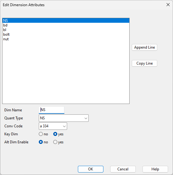
Click Attributes. The Edit Dimension Attributes dialog opens, showing the following attributes:
-
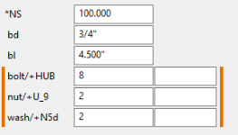
NS (NS) – The nominal size of the flanged connection.
-
bd (Diam) – The diameter of the bolt.
-
bl (Length) – The length of the bolt.
-
bolt (Pieces) – The number of bolts per flanged connection.
-
nut (Pieces) – The number of nuts per bolt.
-
-
Add the following attribute, if needed:
-
wash (Pieces) – The number of washers per bolt.
-
-
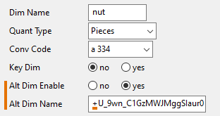
For the bolt, nut, and wash attributes, set Alt Dim Enable to yes, copy the relevant Object ID from the catalog part to the Alt Dim Name field, and insert a plus sign (+) before the ID value.
-
Click OK to close the Edit Dimension Attributes dialog.
-
-
In the Dimensions section, define the range of bolt sizes to include in the bolt set.
-
Click Values. The Dimension Table Edit Tool dialog opens.
-
Click Open Line, and enter the required dimension values. Make sure you leave the alternative dimension fields of the bolts, nuts, and washers empty.
-
Click Open Line to add another bolt size in the same way.
-
When the required bolt sizes are defined, click OK to close the Dimension Table Edit Tool dialog.
-
-
In the Object section, specify the attributes of the bolt set. These may include attributes such as the one that specifies the standard organization and the one that determines whether to use fixed bolt sizes or automatically calculate the bolt length.
-
Click OK to close the Dimension Table Edit dialog.
Next, you can assign the bolt set to the required piping specifications, as described in Assigning bolt sets and gaskets to flange joints.
Using automatic bolt length calculation
The bolt set specifies the default bolt length based on the nominal size of the flanged connection. Instead of using this fixed value, the project administrator can enable automatic bolt length calculation for the bolt set, allowing the bolt length to be dynamically determined based on factors such as flange thickness, gasket thickness, and the number and thickness of nuts and washers.
Configuring the bolt set | Configuring the joint materials | Configuring the GDLs | How bolt length is calculated | How bolt length is selected
Configuring the bolt set
To enable automatic bolt length calculation, set the Bolt length method attribute in the bolt set to Automatic. This setting ensures that Plant Modeller ignores the bolt length values in the bolt set and selects a bolt of suitable length instead.
The threaded extension of the bolt can be defined using the thread_extension length dimension in the bolt set. If this dimension is not defined, the automatic calculation defaults to 1/3 of the bolt diameter for the threaded extension.
Note: If the flanged connection uses stud bolts, the automatic calculation doubles the threaded extension length.
Configuring the joint materials
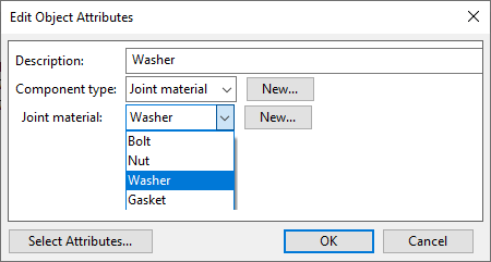
Only joint materials (bolts, washers, nuts) whose Catalog Parts have the Joint material attribute set to the appropriate value will be included in the automatic bolt length calculation. To include joint materials in automatic bolt length calculation, set their Joint material attribute to the appropriate value:
-
Bolt or Stud bolt
-
Nut
-
Washer
Additionally, the bolt, washer, and nut must have a Length dimension defined in their Dimension Tables. If the nut's length is not defined, the automatic calculation will derive it from the bolt diameter.
Configuring the GDLs
If the flange part uses a GDL model, the automatic bolt length calculation requires the connection node in the GDL to have either Flange thickness or Bolt length for tapped holes defined.
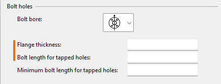
Additionally, you can specify the Minimum bolt length for tapped holes value in the GDL.
For more information on these settings, see Node.
How bolt length is calculated
Flange thickness:
-
For shape-based flanges, flange thickness is taken from the respective value in the dimension table.
-
For GDL-based flanges, flange thickness is taken from the Flange thickness value of the connection node.
Gasket thickness:
-
The thickness of the gasket placed between the flange and the connected object.
Threaded extension:
-
If the bolt set has the thread_extension length dimension, then its value is used.
-
If the bolt set does not have thread_extension, then 1/3 of bolt diameter is used.
Tapped hole minimum length:
-
If the GDL node has Minimum length for tapped holes set to zero, then 1.5 * bolt diameter is used.
-
If the GDL node has Minimum length for tapped holes set to greater than zero, then its value is used.
Moreover, the calculations used to determine the required length of a bolt or stud bolt when connecting a flange to another flange, or when a piece of equipment is placed between the flanges, are described below.
Flange – flange
Machine bolt
Minimum bolt length when the bolt passes through both flanges:
flange thickness + gasket thickness + other flange thickness + thickness of all washers + thickness of all nuts + threaded extension
Minimum bolt length when the bolt only passes through one flange:
flange thickness + gasket thickness + tapped hole minimum length + thickness of all washers + thickness of all nuts
Maximum bolt length when the bolt only passes through one flange:
flange thickness + gasket thickness + other flange Bolt length for tapped holes + thickness of all washers + thickness of all nuts
Stud bolt
Minimum bolt length when the bolt passes through both flanges:
flange thickness + gasket thickness + other flange thickness + thickness of all washers + thickness of all nuts + 2 * threaded extension
Minimum bolt length when the bolt only passes through one flange:
flange thickness + gasket thickness + tapped hole minimum length + thickness of all washers + thickness of all nuts +threaded extension
Maximum bolt length when the bolt only passes through one flange:
flange thickness + gasket thickness + other flange Bolt length for tapped holes + thickness of all washers + thickness of all nuts + threaded extension
Flange – wafer valve – flange
Machine bolt
Minimum bolt length when the bolt passes through both flanges:
flange thickness + gasket thickness + wafer valve length + other gasket thickness + other flange thickness + thickness of all washers + thickness of all nuts + threaded extension
Minimum bolt length when the bolt only passes through one flange:
flange thickness + gasket thickness + wafer valve length + other gasket thickness + other flange tapped hole minimum length + thickness of all washers + thickness of all nuts
Maximum bolt length when the bolt only passes through one flange:
flange thickness + gasket thickness + wafer valve length + other gasket thickness + other flange Bolt length for tapped holes + thickness of all washers + thickness of all nuts
Stud bolt
Minimum bolt length when the bolt passes through both flanges:
flange thickness + gasket thickness + wafer valve length + other gasket thickness + other flange thickness + thickness of all washers + thickness of all nuts + 2 * threaded extension
Minimum bolt length when the bolt only passes through one flange:
flange thickness + gasket thickness + wafer valve length + other gasket thickness + other flange tapped hole minimum length + thickness of all washers + thickness of all nuts + threaded extension
Maximum bolt length when the bolt only passes through one flange:
flange thickness + gasket thickness + wafer valve length + other gasket thickness + other flange Bolt length for tapped holes + thickness of all washers + thickness of all nuts + threaded extension
Flange – wafer valve with tapped holes – flange
Valves with a wafer-style body and a lug with tapped holes require two bolt sets, with their lengths calculated as follows:
-
The bolt length for the wafer-style connection is calculated in the same as way as for a Flange – wafer valve – flange connection.
-
The bolt length for the lug-style connection is calculated in the same way as for a Flange – flange with tapped holes connection. The values for Bolt length for tapped holes and Minimum bolt length for tapped holes are taken from the valve node.
How bolt length is selected
After performing automatic bolt length calculation, the program selects the bolt as follows:
-
For bolts passing through both flanges: The program selects a bolt with a length equal to or greater than the calculated minimum length. There is no maximum length for this type of connection.
-
For bolts passing through only one flange: The program selects a bolt with a length equal to or greater than the calculated minimum length and equal to or less than the calculated maximum length. If multiple bolts meet these criteria, the program selects the bolt with a length closest to the maximum length.